- Our price:USD$
- PriceUSD$
- Use bonus pointspt.
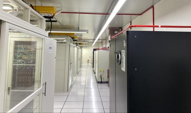
Electronic Data Processing (EDP) Areas
- The following are extracted from FIA Code of Practice Aspirating Smoke Detector (ASD) Systems
Within this type of environment there are a number of issues to be considered in designing the ASD system. These being:
- High Airflow
- Lack of smoke energy
- Resultant low smoke temperature
- Dilution caused by airflow velocities
- Addition of clean air by ventilation systems
Due to these issues it is necessary to protect areas using primary and secondary detection principles. Detection is therefore required at ceiling level, floor void and return grilles of AHU. Ceiling (Roof) voids should also be taken into consideration where necessary.
Dependent upon the area being covered it may be necessary to use separate ASD systems to monitor the specific areas as identified in the preceding paragraph. However, in applications smaller than 150m2 it may be possible to use a single Class A detector to cover the area as identified above (refer to manufacturer for design implications).
Secondary detection spacing, at ceiling levels and within voids, will require the sampling points to be spaced in accordance with clause 8.3.3.2.
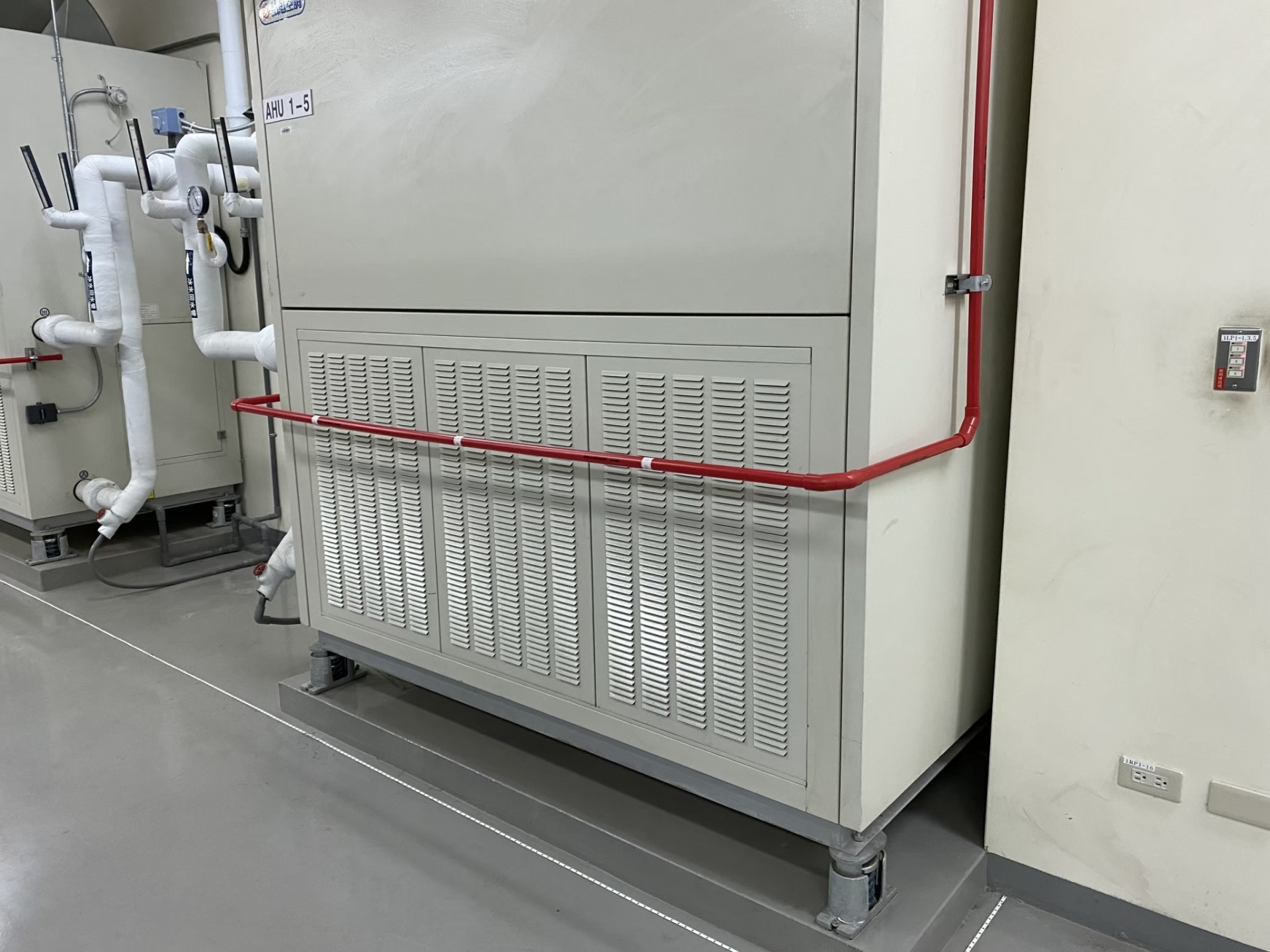
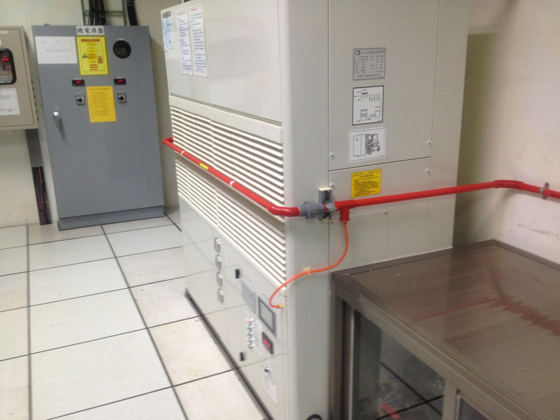
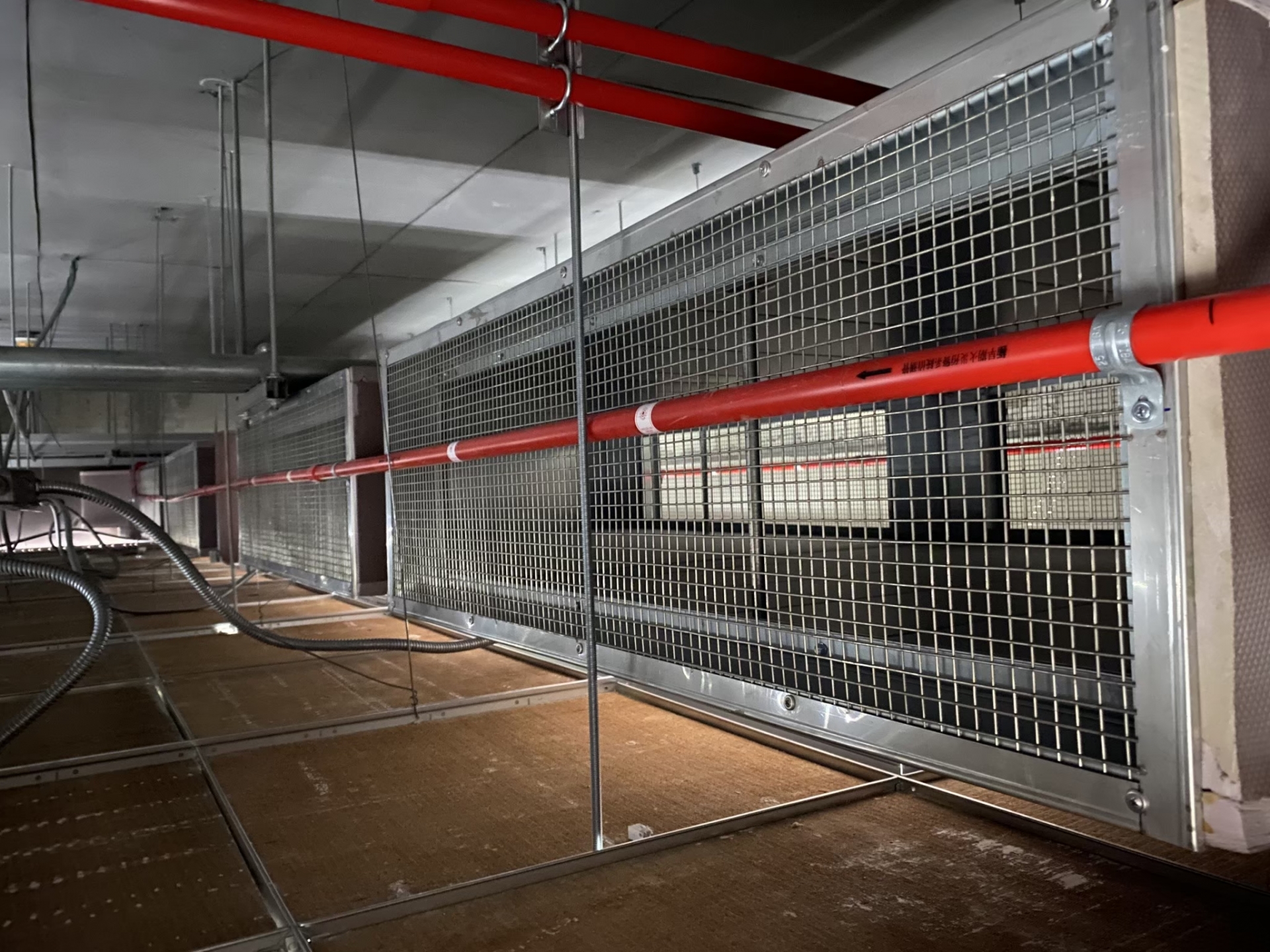
Primary detection of air return grilles can be used to overcome the effects of high airflows, which often prevent the smoke particles from being detected at ceiling level. The maximum number of air return grilles that can be monitored by a single ASD is generally limited to four depending on the air grille size, airflow and the specific ASD being used. Refer to the manufacturer’s recommendations when designing Primary Detection for such areas.
Sampling pipe is required to be installed across the grille with the sample points positioned at a typical angle of 30-60º off centre, into the airflow. Maximum spacing recommendations are given in clause 8.3.3.1. The use of a union socket is recommended to allow the selection of the final orientation during the commissioning of the system and allow maintenance access to the grilles of the AHU.
8.3.3.1 Primary sampling considerations
Generally, the earliest warning of a fire event in high airflow environments is provided by primary sampling, where sampling points cover AHU return grilles. For primary sampling, the following design points must take into consideration:
a. The full air intake grille should be adequately covered by a number of sampling points.
b. It is recommended that each sample point shall have a maximum area coverage of 0.4m2 of the air grille.
Note: typically, three or more sampling holes are used to cover a single air intake.
c. Where large airflows into the grille are encountered (eg >4m/s) special arrangements may be necessary, such as positioning the pipe away from the grille using stand-off brackets.
d. It is generally the case that airflows into the grille follow the louvers (where fitted) the pipe should be positioned in the main air-stream.
e. Sampling holes are typically positioned at an angle of 30-60o off centre, into the airflow.
f. Maintenance access to the air-handling unit should not be restricted by the sampling pipe. Convenient removal of the pipe should be accommodated.
g. Internal mounting of the pipe is sometimes desirable, but requires special consideration due to the internal operation of the air-handling unit (internal dampers and louvers) and the increased negative pressures relative to the pressured inform of the air return grille.
When mounting the sampling pipe, it is generally recommended that the samples are taken upstream of any filtration to avoid the high negative pressures and the possibility of the filters removing smoke before it reaches the ASD system. See section 10.2 (EDP areas) and Section 10.7 (Duct detection).
8.3.3.2 Secondary detection hole spacing in EDP/high airflow environments
To combat the effects of high airflow and subsequent smoke dilution prescriptive design Standards such as BS 6266:2011 and VDE 0833 Part2:2009 Annex E specify closer spacing of point detectors mounted on ceiling or in voids. These spacing rules are generally intended for point detectors and may be used where the ASD is being installed to meet the prescriptive design goals, because each sampling hole has equivalent sensitivity to a standard point detector. However, in many cases these closer spacing requirements are not directly applicable to ASD and the latest revision of BS 6266 provides some useful adjustments that may be applied to the area covered by each sampling hole. For convenience these adjustments are reproduced below.
BS 6266:2011 recommendations state:
Detectors within the electronic equipment installation should be spaced such that the effective area coverage of each point or sampling hole is 25m2 or less. Adjustments to this maximum area should be made as follows. More than one adjustment can be applied for a given application.
a. Reduce by:
(1) 5m2 if airflows >1 m/s and ≤4 m/s are present in >25% of the space;
(2) 10m2 if airflows >4 m/s are present in >25% of the space.
b. Increase by 10m2 if the air-conditioning is to be shut off by early warning detection at the air return vents.
c. Increase by 5m2 if asymmetric spacing of the detectors/holes is provided whereby a greater density of point/holes is provided across the prevailing direction of flow.
d. Increase by 5m2 if the detection system deployed has enhanced sensitivity. (For example, a sensitivity equivalent to a Class B ASD sampling hole.)
e. Increase by 5m2 if the detection system used is an integrating type detector (ie ASD or optical beam).
f. Reduce by 5m2 if coincident detection is provided based on detectors in two zones operating (as opposed to any two addressable detectors).
g. For floor and ceiling voids (up to 1.5m high), adjust as follows according to the level of ventilation present.
(1) Reduce by 5m2 for floor and ceiling voids which are ventilated or which are used as part of the ventilation system.
(2) For floor and ceiling voids without ventilation (ie airflow = 0):
(i) Increase by 5m2 for voids with a smooth ceiling.
(ii) Reduce by 5m2 when the void has very shallow beams (eg <5% of the void height).
(iii) Reduce by 10m2 when the void has shallow beams (eg between 5% and 10% of the void height).
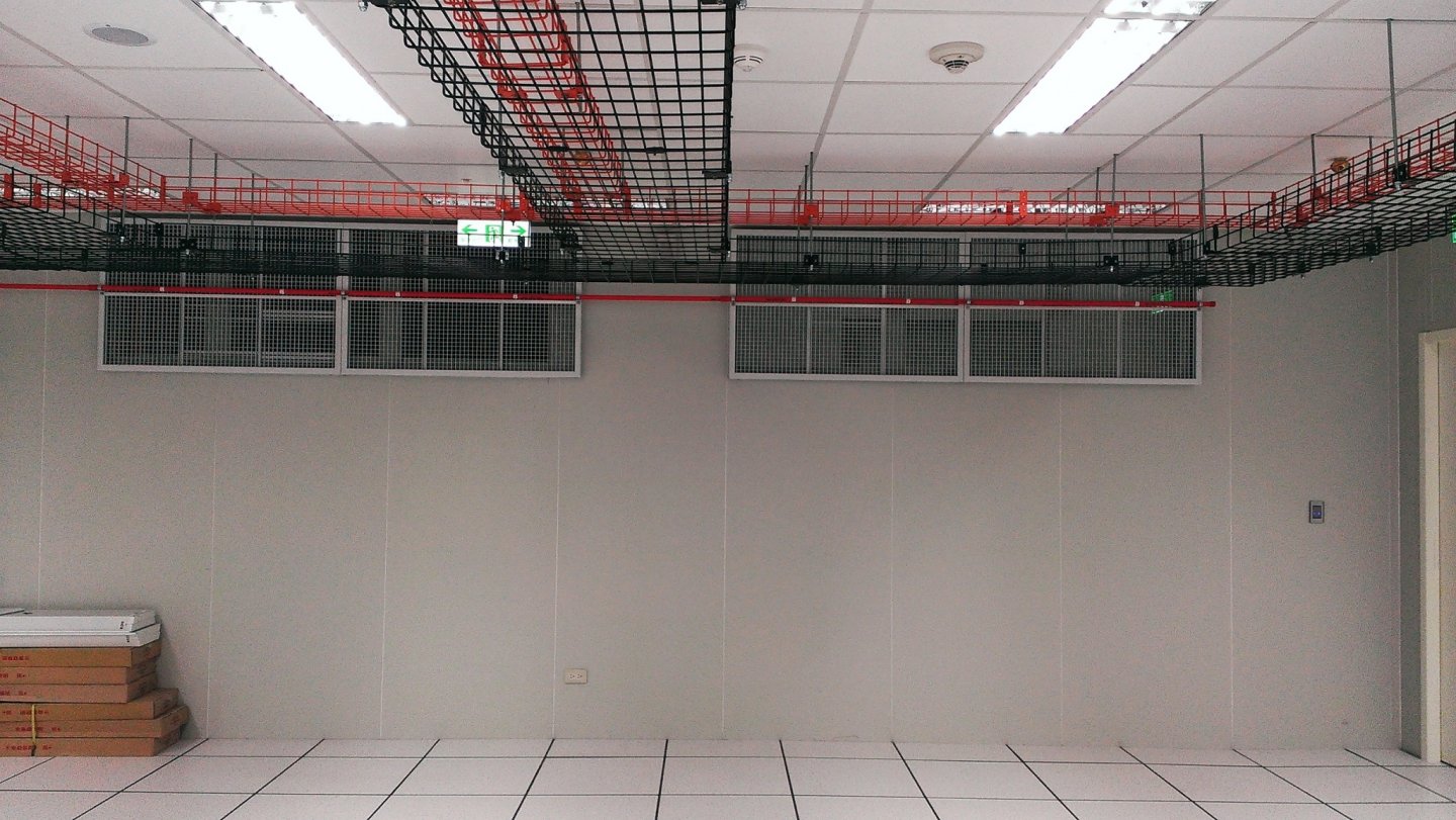
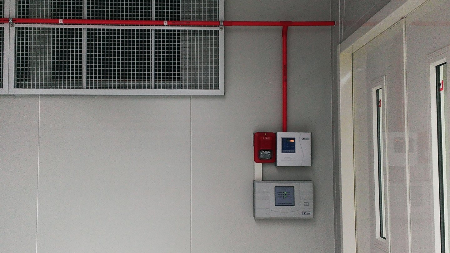
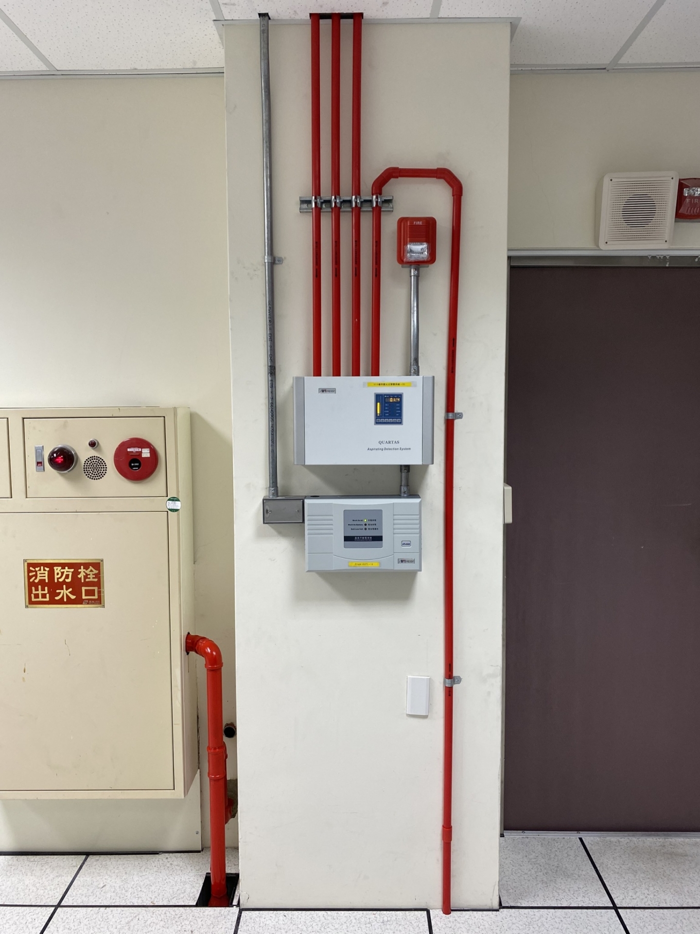
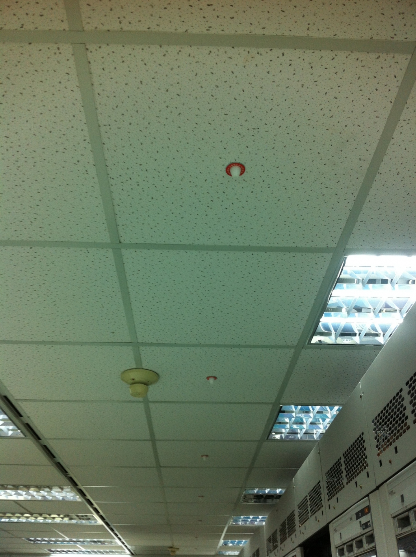
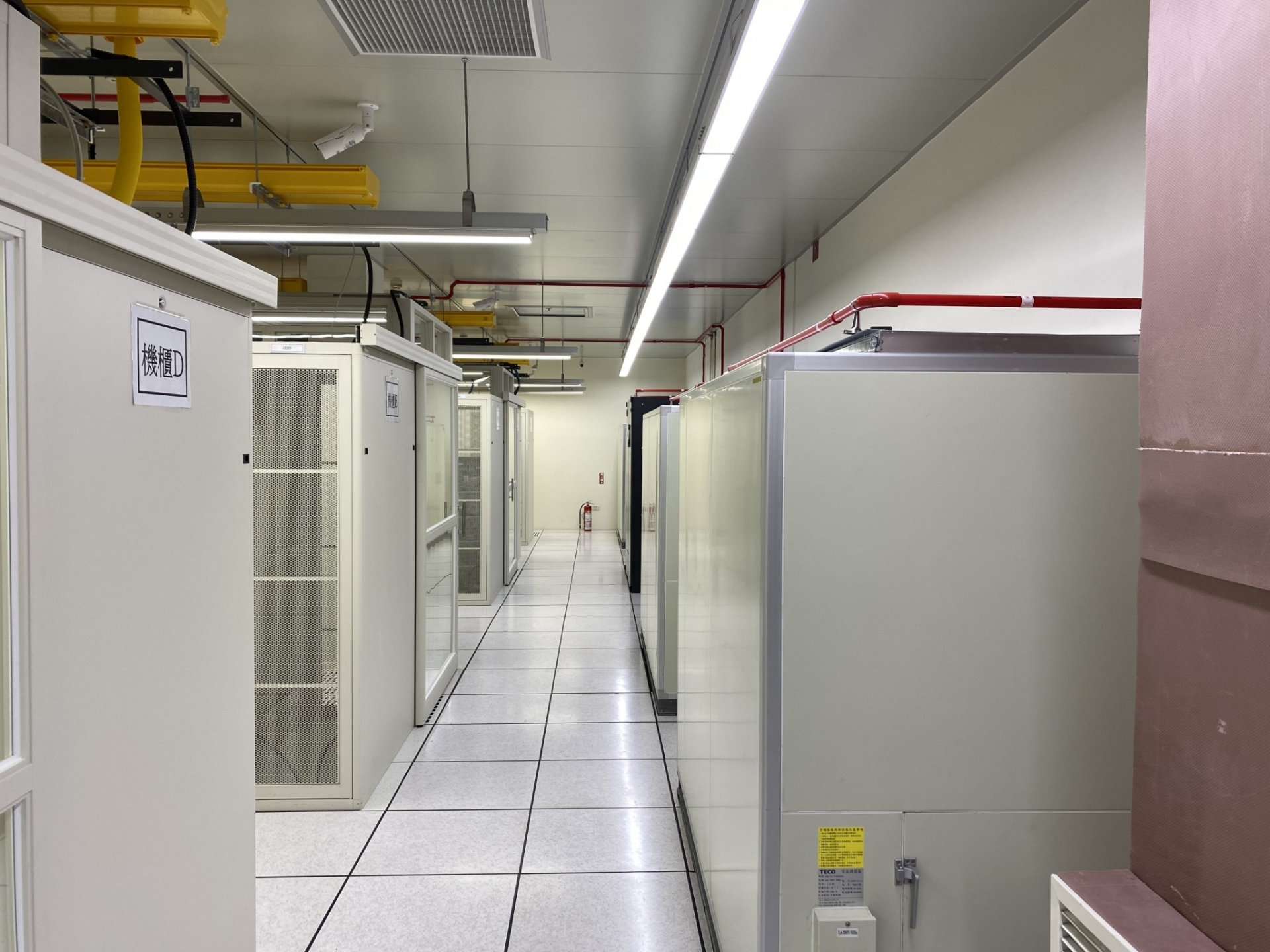
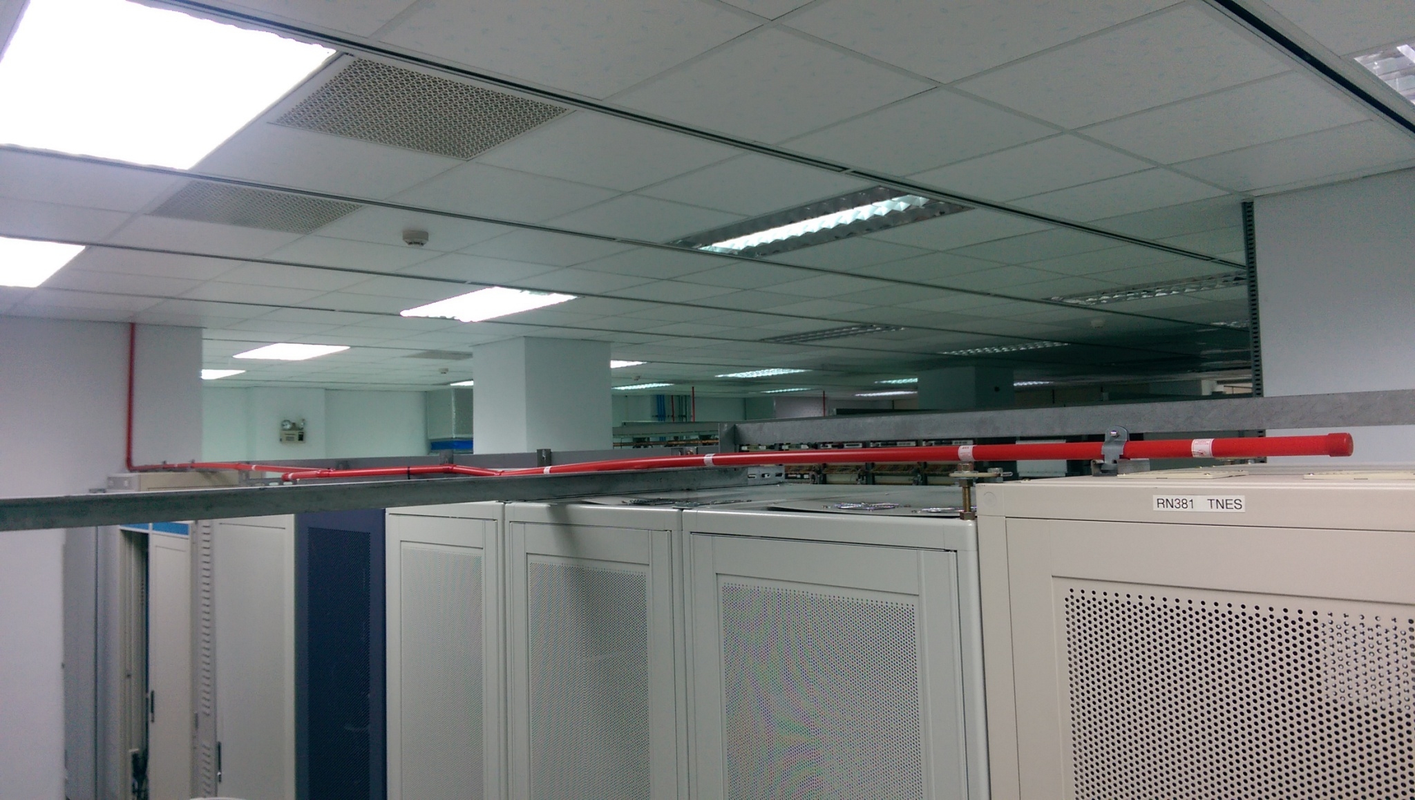
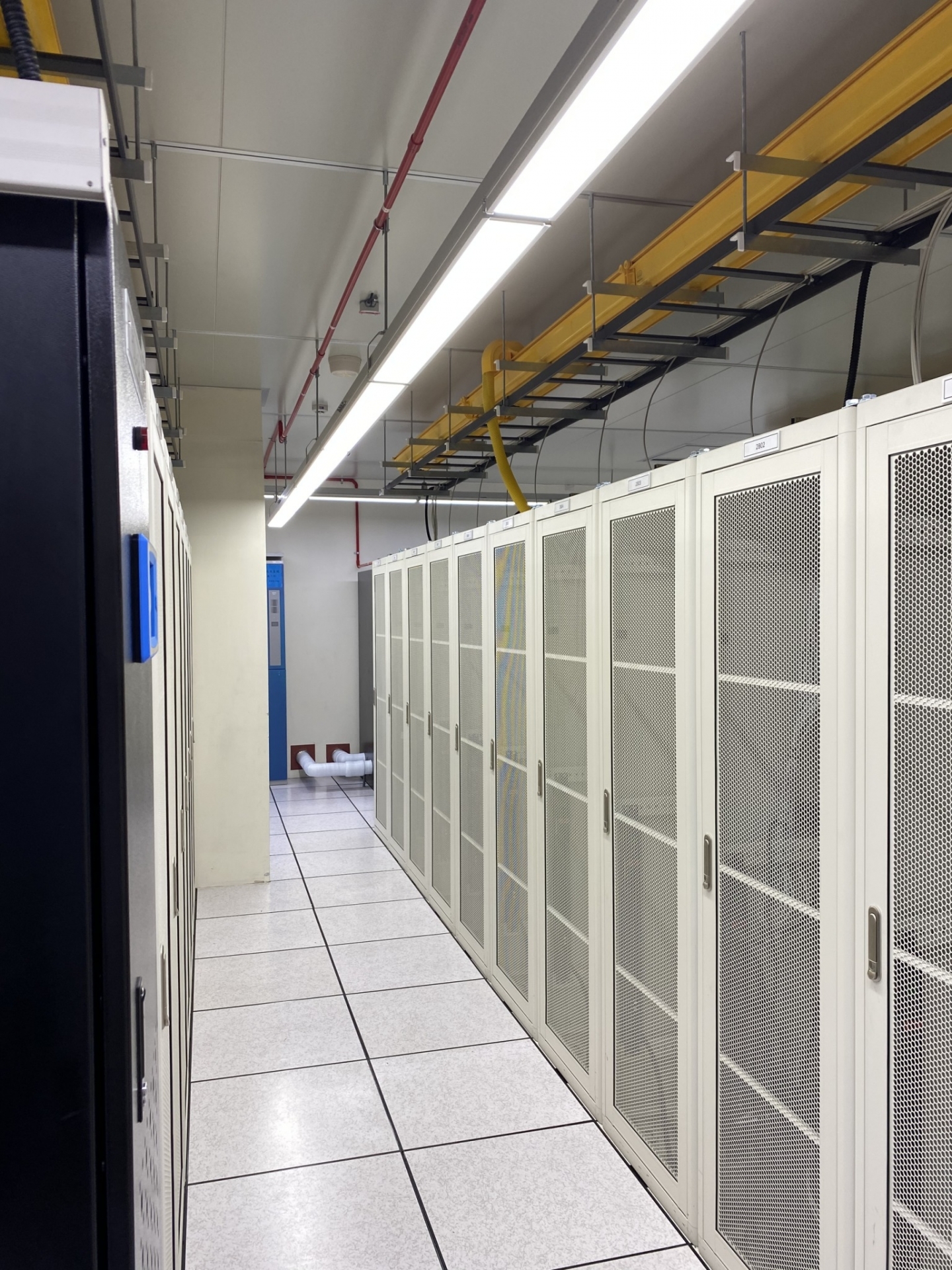
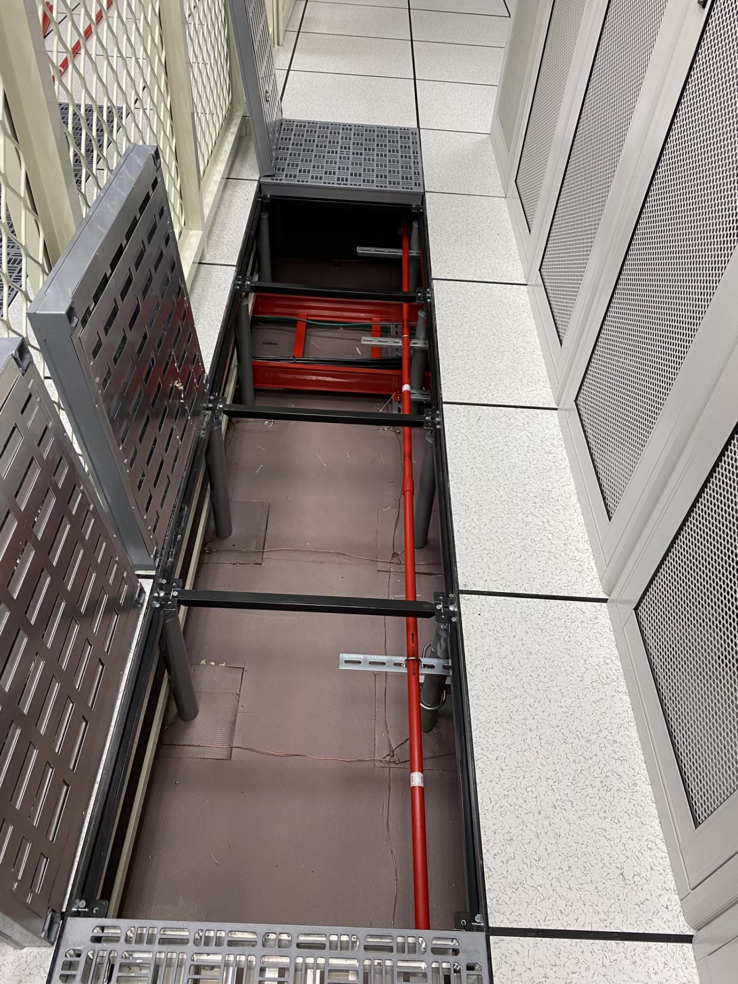
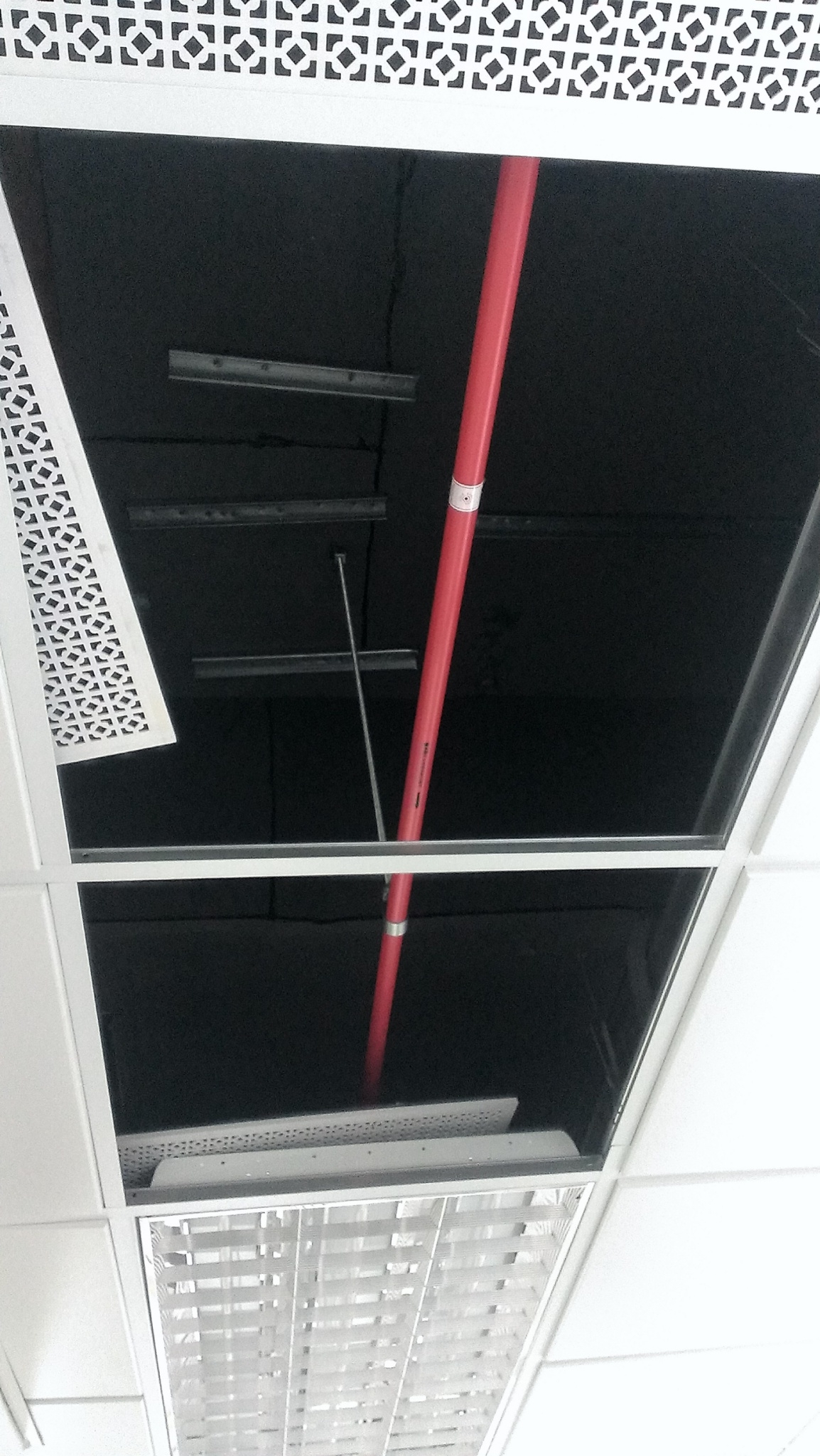
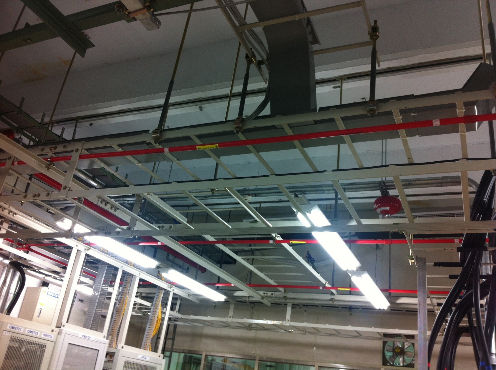
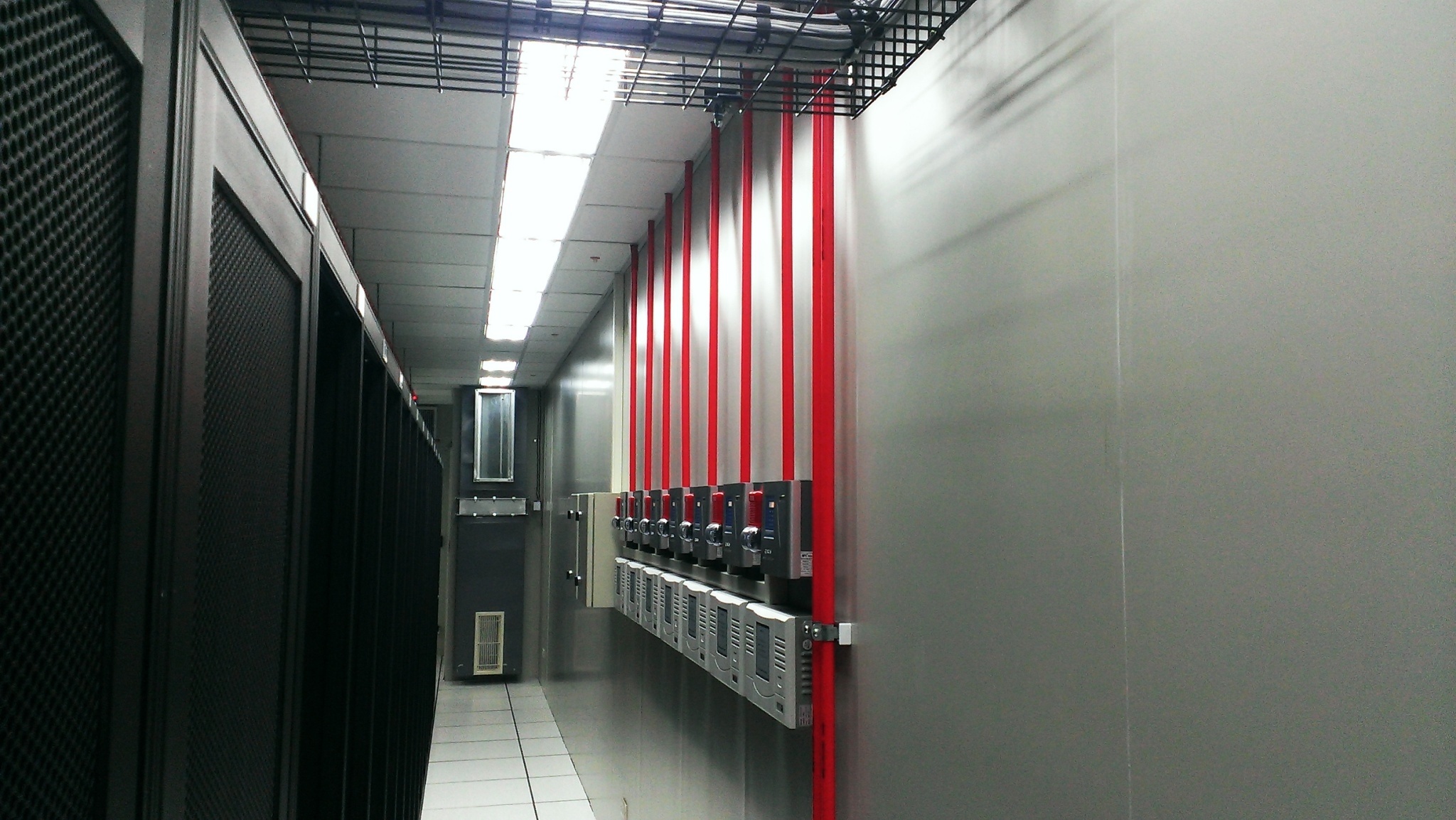
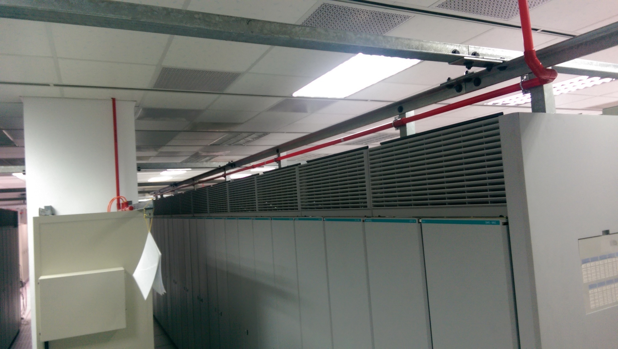
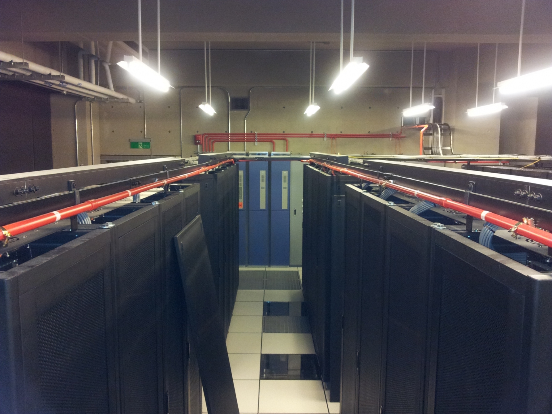
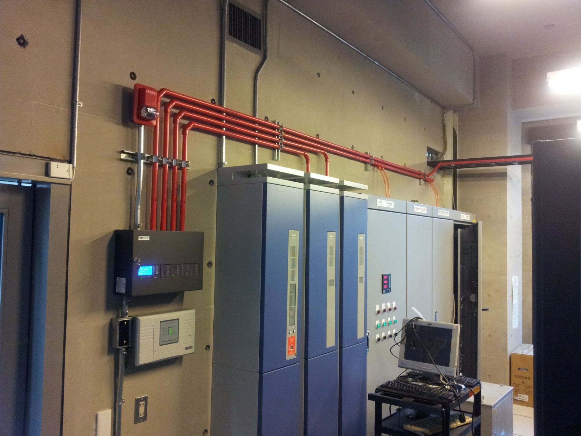
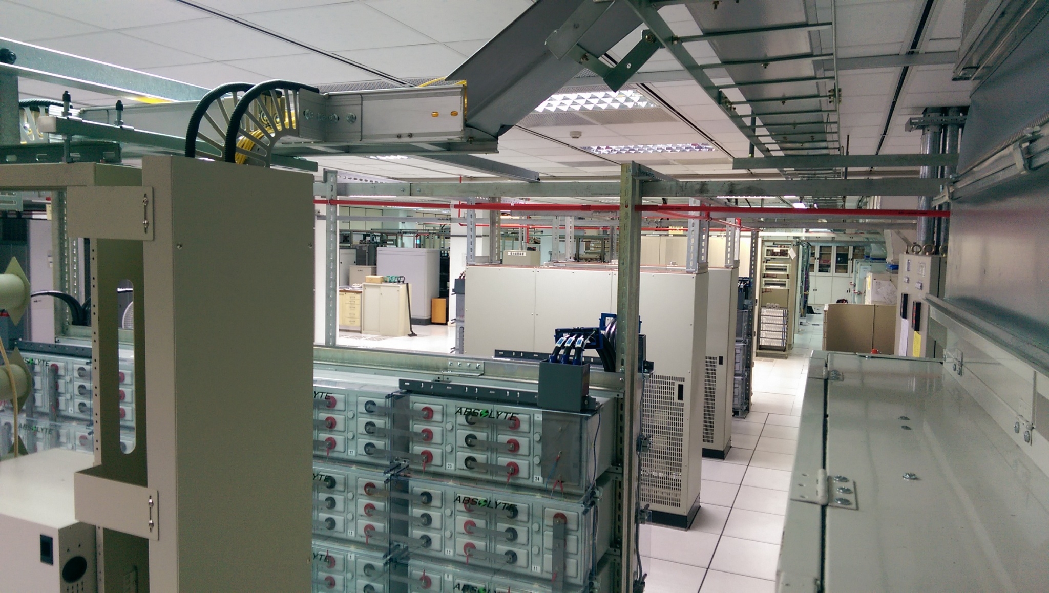
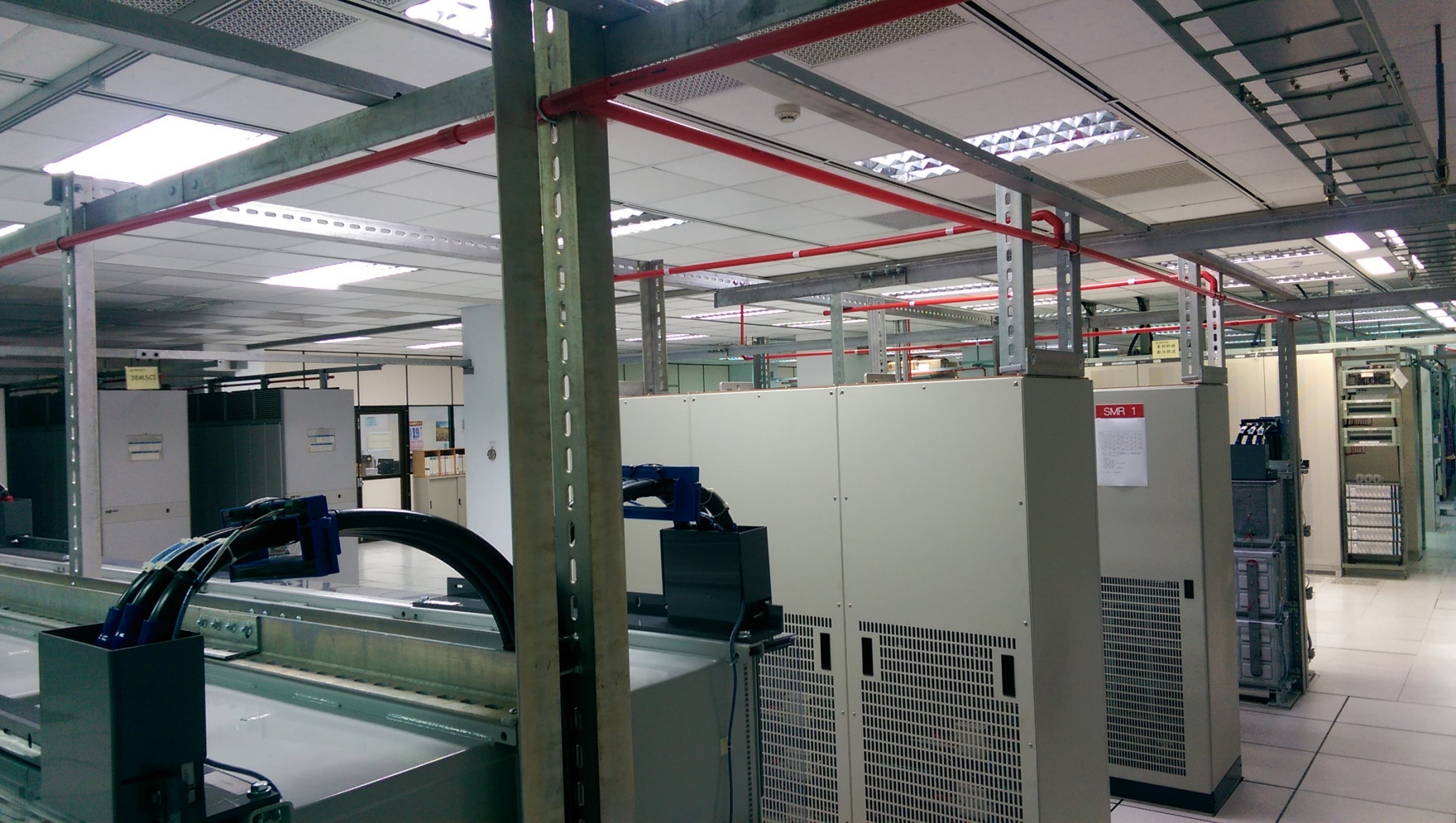
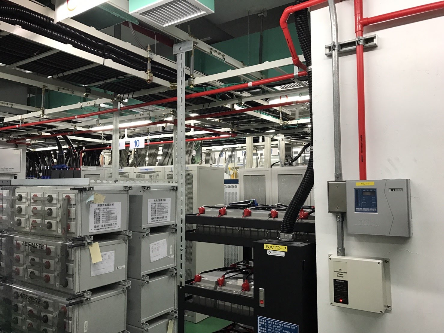
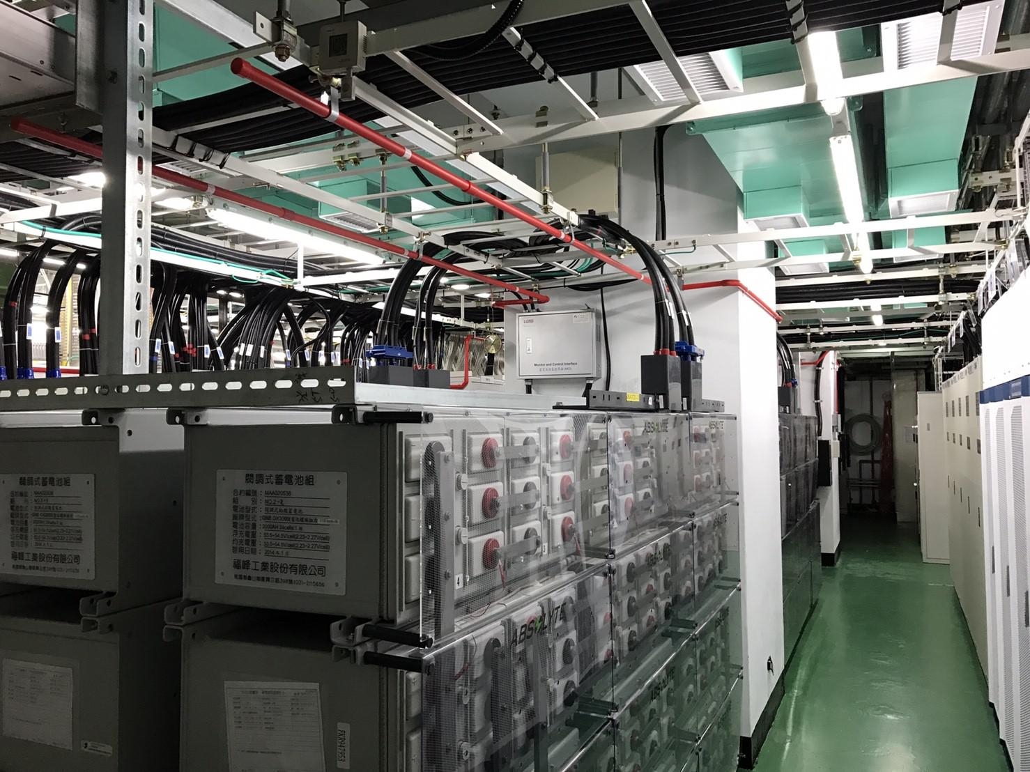
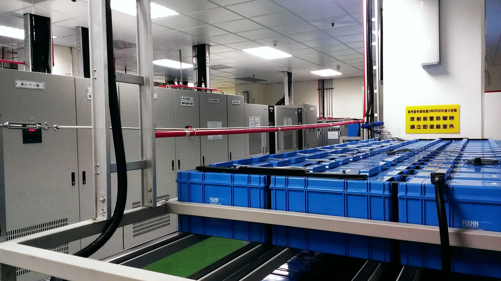
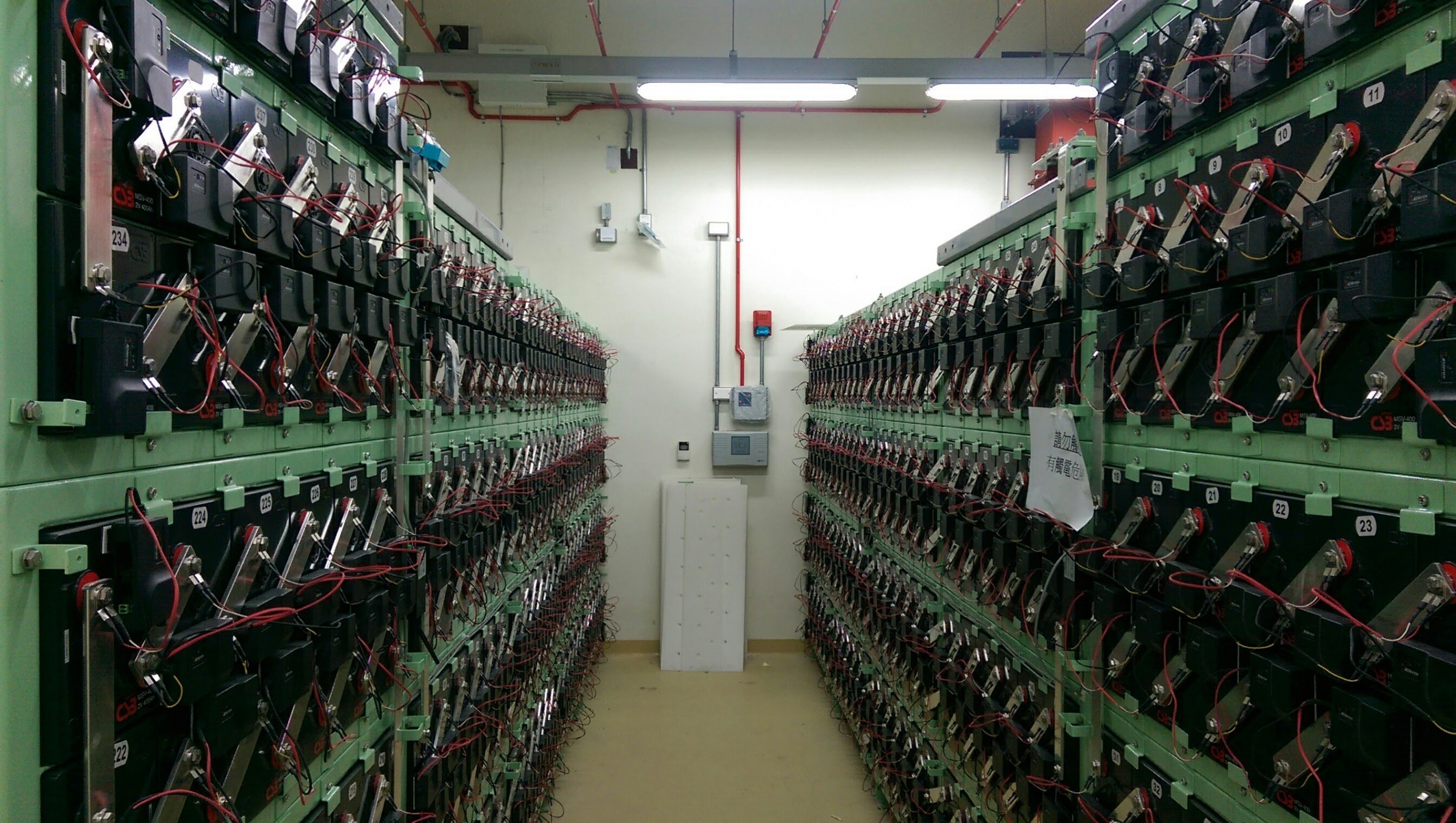
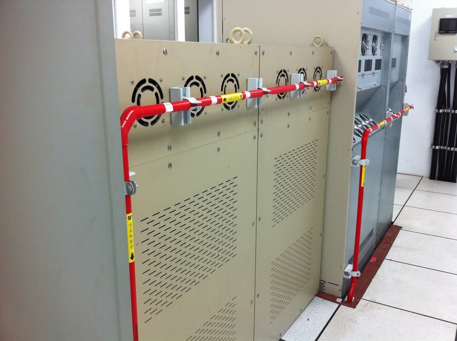
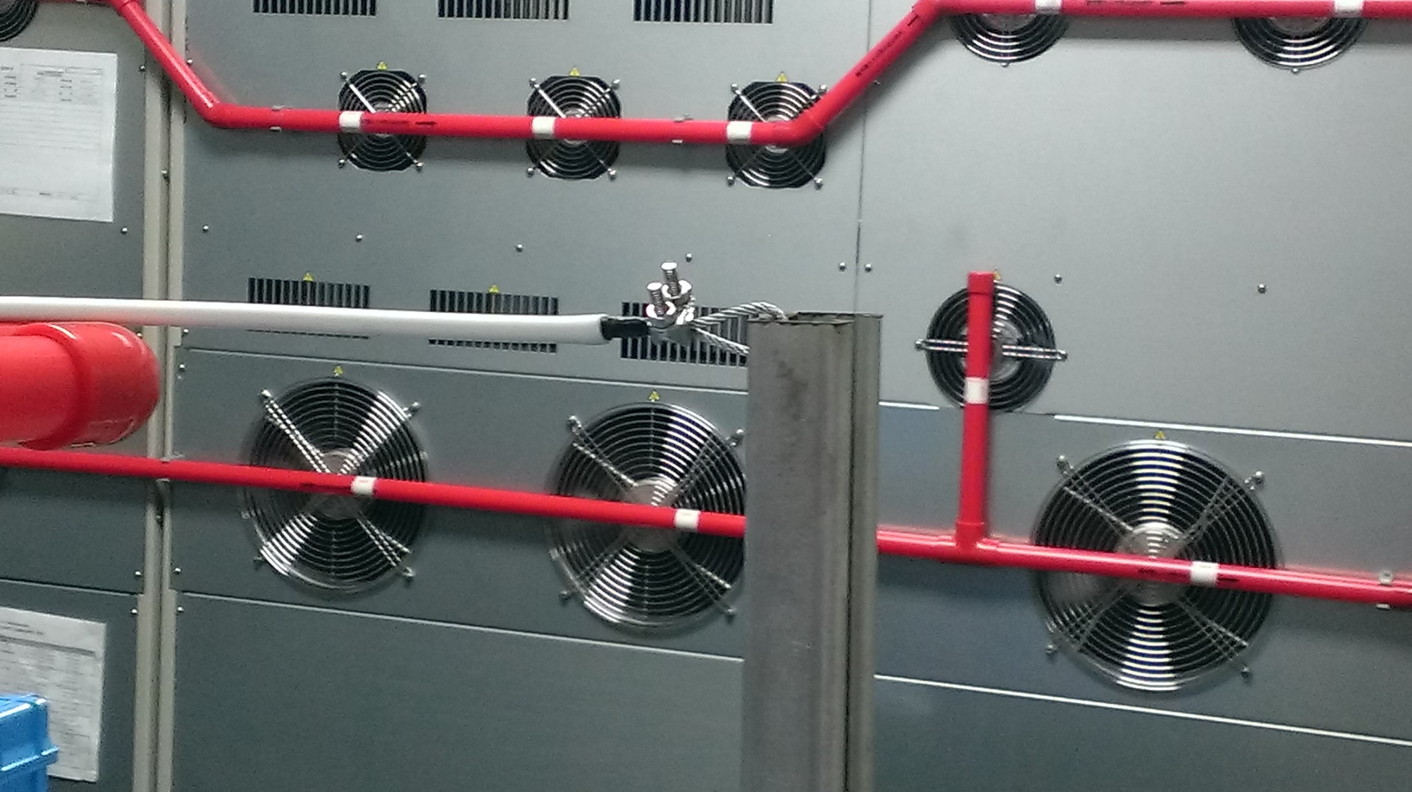
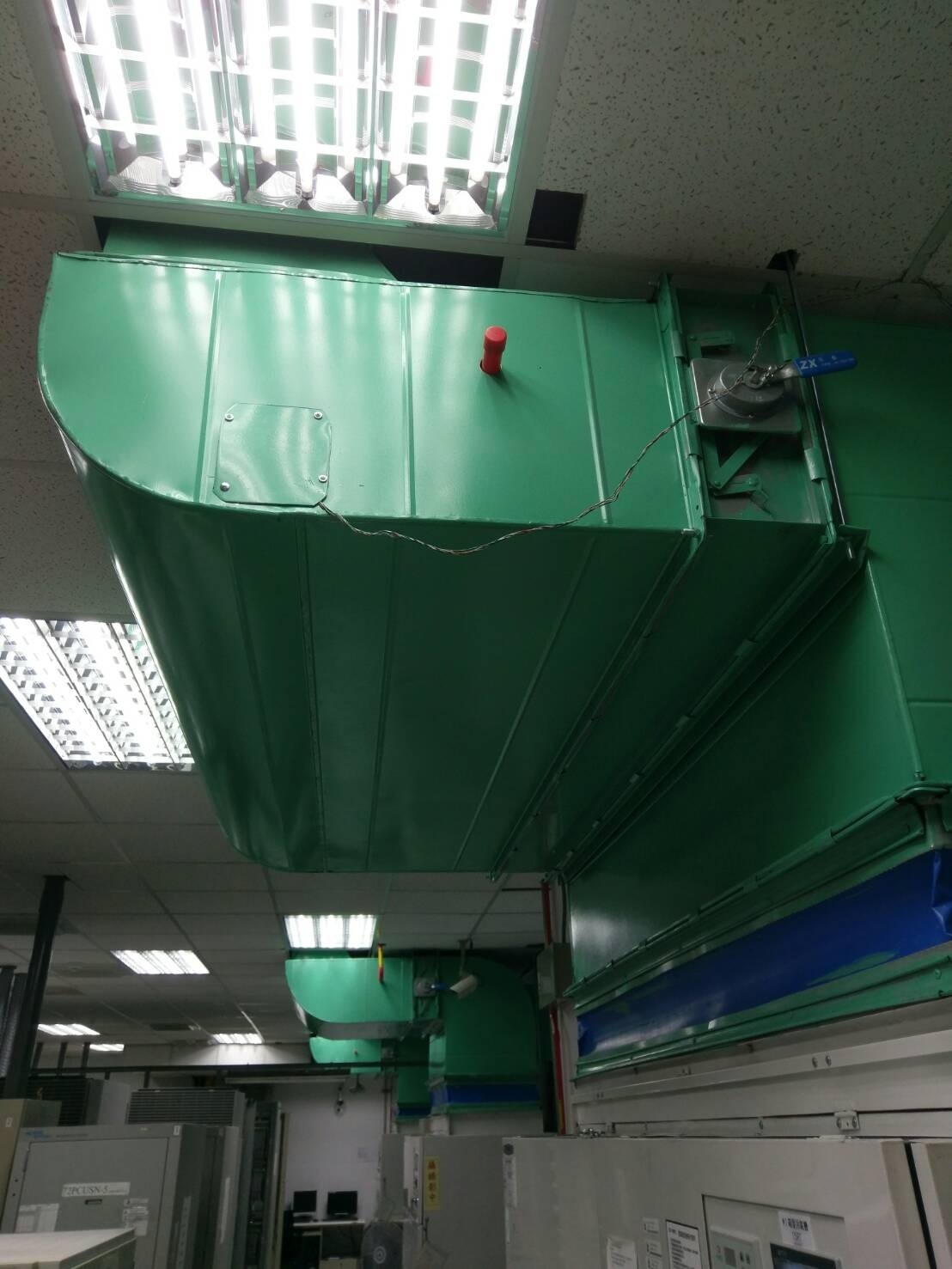
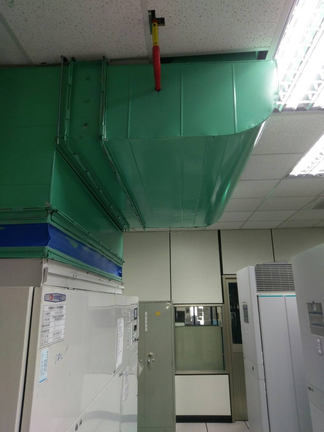
Data Center/EDP/Telecom Application Photos
PARTIAL CUSTOMER LIST
Telecom/IDC
- Chunghwa Telecom Mobile ( Telecommunication Room Communication Branch)
Kaohsiung Shiquan/Juemin/ ErlingTa
Tainan Yongkang
Taichung Changer - Chunghwa Telecom Toufen site: Cloud Modular
- Taiwan Stock Exchange Yang De Building: Substation/Data Center/Electrical Room/UPS Room/Battery Room
- HWACOM SYSTEMS INC
- Bureau of Education,Tainan City Government
- China Telecommunications Group Co.,Ltd
Airport
- Taipei Songshan Airport Immigration: Computer Room
Bank
- Taiwan Stock Exchange Banqiao Data Center Project 1 & 2
- South China Insurance
- Taishin International Bank Neihu
- Industrial Bank of Taiwan Neihu
Judicial
- Hualien High Court
- Hualien District Court
- Hualien High Court Sindian Summary Court
- Hualien District Court Sindian Summary Court
- Our price:USD$
- PriceUSD$


